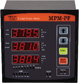
An Automatic Power Factor Controller that measures the load power factor in real time and automatically switches capacitor banks in and out, improving energy efficiency.
MPM-PF (6 / 12 circuits)
Overview
The MPM-PF improves energy efficiency through automatic power factor management. Built around a high-performance DSP and MCU, it measures a wide range of electrical quantities in real time and is designed to control the capacitor panel banks connected on the load side by either power factor or reactive power.
It measures more than 20 electrical quantities and can control up to 12 capacitor BANKS. Two ALARM outputs are included, and built-in communication enables remote monitoring.
Features Key advantages unique to the MPM-PF
- Digital power meter + automatic power factor controller in one
- User-configurable minimum control range, from 1%
- Cumulative switching-cycle count per capacitor bank
- Cumulative energized-time count per capacitor bank
- Automatic, sequential, and circular control modes
- Manual capacitor on/off function
General Specifications
| Power supply | 100 ~ 240Vac (60Hz) / 110Vdc |
|---|---|
| Power consumption | 5VA |
| Voltage input | Up to 470Vac (LINE to LINE), burden 0.02VA |
| Current input | Rated current 5A (max. 10A), burden 0.15VA |
| Insulation | Galvanic isolation and EMI filter |
| Operating temperature | -20℃ ~ 60℃ |
| Operating humidity | 0 ~ 90% (NONE CONDENSING) |
Control Functions
| Bank setup | Number of banks | 0 ~ 12 (form-A contacts) |
|---|---|---|
| Number of ALARM outputs | 2 (form-A contacts) | |
| Capacitor rating setting | 1 ~ 9,999 kvar (AUTO / MANUAL setting) | |
| Delay Time | 3 ~ 3,000sec | |
| Dead Time | 3 ~ 3000sec | Allowance time for charge/discharge |
| Maximum power factor setting | 0.95 ~ 1 ~ -0.96 | (− = leading) |
| Minimum power factor setting | 0.50 ~ 0.95 | |
| Reactive power setting (optional) | 0.95 ~ 1 ~ -0.96 | (− = leading) |
| Control mode | Power factor / reactive power | Auto setting and control |
| Sequential control | ||
| Circular control | ||
| Dead band | Below 10% of CT input peak current | |
Measurement Functions
| Item | Unit | Range | Accuracy | Remarks |
|---|---|---|---|---|
| Voltage (3-phase) | V | 0V ~ 9,999 KV | 0.3% F.S | — |
| Current (3-phase) | A | 0 ~ 9,999 KA | 0.3% F.S | — |
| Frequency | Hz | 45.0 ~ 65.0 | 0.3% F.S | — |
| Power factor | % | -1.00 ~ 1.00 | 0.5% F.S | — |
| Per-phase power factor | % | -1.00 ~ 1.00 | 0.5% F.S | Via comm. DATA |
| Active power | kW | 0 ~ 9,999 MW | 0.5% F.S | — |
| Per-phase active power | kW | 0 ~ 9,999 | 0.5% F.S | Via comm. DATA |
| Reactive power | Kvar | 0 ~ 9,999 MVar | 0.5% F.S | — |
| Per-phase reactive power | Kvar | 0 ~ 9,999 MVar | 0.5% F.S | Via comm. DATA |
| Apparent power | kVA | 0 ~ 9,999 MVA | 0.5% F.S | — |
| Per-phase apparent power | kVA | 0 ~ 9,999 MVA | 0.5% F.S | Via comm. DATA |
| Active energy | kWh | 0 ~ 9,999 MWh | 0.5% F.S | — |
| Active power peak | kW | 0 ~ 9,999 MW | 1% F.S | — |
| Voltage phase angle | ° | — | 0.5% F.S | 3-phase 4-wire wiring |
Communication Specifications
| Communication port | RS-485 1 Port or RS-232C 1 Port (optional) |
|---|---|
| Protocol | Modbus RTU |
| Communication method | RS-485 Half Duplex 2Wire |
| Baud rate | 4800, 9600, 19200, 38400 bps |
| Max. connected units | 32 units |
| Cable length | Max. 1.2km |
Model Variants
MPM-PF : 6 circuits (6 BANK) , 12 circuits (12 BANK)
MPM-PF-300
Overview
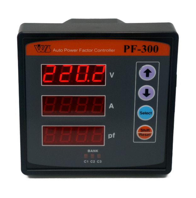
MPM-PF300 improves energy efficiency by automatically managing both leading and lagging power factor. Using a high-efficiency DSP and MCU, it measures the load power factor in real time and switches capacitors in and out accordingly.
Thanks to its wide-angle TYPE housing, it can replace an existing analog power factor meter without additional panel cutting, and it can control up to 3 capacitors.
General Specifications
| Power supply | 100 ~ 220Vac (60Hz) |
|---|---|
| Power consumption | 5VA |
| Voltage input | Up to 470Vac (LINE to LINE), burden 0.02VA |
| Current input | Rated current 5A (max. 10A), burden 0.15VA |
| Insulation | Galvanic isolation and EMI filter |
| Operating temperature | -20℃ ~ 60℃ |
| Operating humidity | 0 ~ 90% (NONE CONDENSING) |
Control Functions
| Bank setup | Number of banks | Max. 3 (form-A contacts) |
|---|---|---|
| Delay Time | 3 ~ 3000sec | Set a sufficient time allowing for capacitor charge/discharge |
| Dead Time | ||
| Maximum power factor setting | 0.95 ~ 1 ~ -0.96 | (− = leading) |
| Minimum power factor setting | 0.80 ~ 0.95 | |
| Reactive power setting (optional) | 0.95 ~ 1 ~ -0.96 | (− = leading) |
| Control mode | FIFO | Fixed |
| Dead band | Below 5% of CT input peak current | |
Measurement Functions
| Item | Unit | Range | Accuracy | Remarks |
|---|---|---|---|---|
| Voltage (R-phase) | V | 40V ~ 9,999 KV | 0.5% F.S | — |
| Current (R-phase) | A | 0.1 ~ 9,999 KA | 0.5% F.S | — |
| Power factor | % | -1.00 ~ 1.00 | 1.0% F.S | — |
Communication Specifications
| Communication port | RS-485 1 Port or RS-232C 1 Port (optional) |
|---|---|
| Protocol | Modbus RTU |
| Communication method | RS-485 Half Duplex 2Wire |
| Baud rate | 4800, 9600, 19200, 38400 bps |
| Max. connected units | 32 units |
| Cable length | Max. 1.2km |
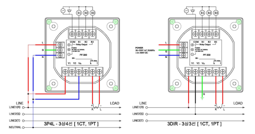
Wiring Diagram